
GEMAC CAN-Bus Tester 2
$10,142.00
![]()
Possibilities
The CAN-Bus Tester 2 is a widely used measuring device for control of bus parameters. The success story starts already in year 2002 with the first model. The hardware was completely redesigned in version 2. The corresponding software is still developed and has been enhanced with extensive updates.
Check the setup of the bus before you switch on with the bus wiring test, measure under running conditions down on the physical layer and analyses data of the nodes with the protocol monitor. The long time monitor shows scattered errors and creeping signal loss.
The trigger output makes it possible to show data of only one node of the bus.
The great box contents within the service case with big adapter set makes it possible to use the device out of the box in many environments. You can safe your measurements and print a status protocol directly from the software.
Bus Systems
The measuring device works in the networks CAN, CANopen, DeviceNet and SAE J1939.
To know more about this product check the youtube link.
This product will take upto 5 weeks for delivery.
Description
66GEMAC CAN-Bus Tester 2
Pos?si?bi?li?ties
The CAN-Bus Tes?ter 2?is a?wide?ly used mea?su?ring device for con?trol of bus para?me?ters. The suc?cess sto?ry starts alre?ady in year 2002 with the first model. The hard?ware was com?ple?te?ly rede?si?gned in ver?si?on 2. The cor?re?spon?ding soft?ware is still deve?lo?ped and has been enhan?ced with exten?si?ve updates.
Check the set?up of the bus befo?re you switch on with the bus wiring test, mea?su?re under run?ning con?di?ti?ons down on the phy?si?cal lay?er and ana?ly?ses data of the nodes with the pro?to?col moni?tor. The long time moni?tor shows scat?te?red errors and cree?ping signal loss.
The trig?ger out?put makes it pos?si?ble to show data of only one node of the bus.
The gre?at box con?tents wit?hin the ser?vice case with big adap?ter set makes it pos?si?ble to use the device out of the box in many envi?ron?ments. You can safe your mea?su?rements and print a?sta?tus pro?to?col direct?ly from the soft?ware.
Bus Sys?tems
The mea?su?ring device works in the net?works CAN, CANo?pen, Device?Net and SAE J1939.
The CBT2 can also be used for mea?su?rements in other bus sys?tems based on the CAN stan?dard. The?se inclu?de Iso?bus, NMEA 2000 and Safe?ty?Bus P, but also Ener?gy?bus, CAN?a?e?ro?space and ARINC825. Niche bus sys?tems are Mil?CAN and CANo?pen Lift.
Licence Model
In the basic con?fi?gu?ra?ti?on the CAN-Bus Tes?ter 2?is enab?led for bus sys?tem CAN. You can do all phy?si?cal mea?su?rements wit?hin this sys?tem.
Addi?tio?nal licen?ses are offe?red to the sys?tems CANo?pen, Device?Net and SAE J1939. With them it is much easier to assign the messa?ges to the real nodes.
The optio?nal pro?to?col moni?tor is for logi?cal bus ana?ly?sis in the bus sys?tems CAN (trans?mit /?recei?ve), CANo?pen (recei?ve) and SAE J1939 (recei?ve).
The user soft?ware is free to down?load?and use, only for mea?su?rements with the CAN-Bus Tes?ter 2?it has to be unlo?cked.
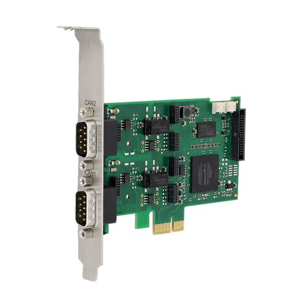
Con?nec?tions
Power Sup?ply
The device works with 9 ? 36?V. Only for the Bus Wiring test min. 24?V?are nee?ded.
USB Port
Con?nect your win?dows PC or lap?top here.
CAN and CAN pro?be port
Two 9-pin D-Sub ports are for con?nec?tion to the bus and for pro?bes
Trig?ger Out?put
For fur?t?her mea?su?rements with a?digi?tal sto?ra?ge oscil?lo?scope the CAN-Bus Tes?ter 2?can be used as trig?ger source.
Two Devices in one
The CAN-Bus Tes?ter 2?is basi?cal?ly a?2-in-1 device. One part is respon?si?ble for the exten?si?ve mea?su?rements on the phy?si?cal level. 64-fold sam?pling of each indi?vi?du?al bit makes detail?ed eva?lua?ti?on pos?si?ble.
The other part is a?CAN-to-USB inter?face for com?pre?hen?si?ve pro?to?col ana?ly?sis. Both parts of the device can work inde?pendent?ly of each other or simul?ta?neous?ly and toge?ther.
Among many other things, it is pos?si?ble to stop the pro?to?col ana?ly?sis auto?ma?ti?cal?ly if the phy?si?cal mea?su?ring device has detec?ted a?pro?blem. In this way, the data traf?fic can be eva?lua?ted imme?dia?te?ly befo?re an error occurs. You don?t have to search through long lists of tele?grams, the end of the list is the rele?vant point.
Bus Wiring Test
With the wiring test, it is pos?si?ble to deter?mi?ne line short-cir?cuits, line breaks, the bus ter?mi?na?ti?on, the loop?resis?tan?ces of the CAN line and the CAN power sup?ply line, and the over?all line length.
To ensu?re cor?rect?bus cabling, it is recom?men?ded to per?form the wiring test at the begin?ning of any plant mea?su?rements.
Node Mea?su?rement
Con?nect the CAN-Bus Tes?ter 2?to your bus line. Your should see a?green led on your dis?play, sho?wing that the?re is data traf?fic.
First start the baud rate scan, then scan for nodes. All messa?ges on the bus are now recei?ved and ana?ly?sed, the nodes with their ID are listed. Name the nodes if you want for bet?ter over?view.
With the mea?su?rement ?all sta?ti?ons view? you get an over?view of the qua?li?ty levels of the signals. The bar dia?gram makes it ease to com?pa?re. At con?ti?nuous mode you will addi?tio?nal see the min/?max?values. You can easi?ly com?pa?re to a?saved mea?su?rement.
The mea?su?rement ?one sta?ti?ons view? shows the sin?gle values of one node and shows a?phy?si?cal and logi?cal deco?ded oscil?lo?gram. Qua?li?ty level, edge steep?ness and dis?tur?ban?ce free vol?ta?ge ran?ge are the three show?ed mea?su?rands. By star?ting a?con?ti?nuous mea?su?rement you will also see min/?max of qua?li?ty level and the varia?ti?on of the dis?tur?ban?ce-free vol?ta?ge ran?ge.
Online Moni?tor
This mea?su?rement runs con?ti?nuous?ly and com?pa?res with?given thres?holds. If it over?runs the thres?hold the error will be regis?te?red. At sin?gle mea?su?rement mode it stops and the faul?ty messa?ge is show?ed in the oscil?lo?scope view. In con?ti?nuous mode the error is?mar?ked in a?time dia?gram. So you show when your thres?hold was overrun?ed or if a?error?frame has occur?red.
The obser?ved values are
Active-Error /?Pas?si?ve-Error Frames
Over?load Frames
Ack?now?ledge Error
Gene?ral qua?li?ty level (0 ? 100 %)
Dis?tur?ban?ce-free vol?ta?ge ran?ge?(mini?mum noise free?dif?fe?ren?ti?al vol?ta?ge)
Edge steep?ness?(worst rising and fal?ling edge of a?messa?ge)
Addi?tio?nal?ly to this logi?cal and phy?si?cal mea?su?rements the CAN-Bus Tes?ter 2?is con?ti?nuous?ly deter?mi?ning bus traf?fic load, bus sta?tus and the optio?nal CAN sup?ply vol?ta?ge.
The soft?ware can be adjus?ted in a?way, that a?simul?ta?neous?ly run?ning Recei?ve in the pro?to?col moni?tor is stop?ped in case of an error. So it is easier to ana?ly?se that data traf?fic that was on the bus befo?re the error occurred.
Pro?to?col Moni?tor
Many fea?tures of the CAN?vi?si?on Pro?to?col Moni?tor are build in the CAN-Bus Tes?ter 2?user soft?ware. It is easi?ly unlo?cked when you buy a?licen?se.
Inform yours?elf about the ran?ge of fea?tures of CAN?vi?son here.
Main dif?fe?rence is the net?work capa?bi?li?ty, this can only be used with the full ver?si?on of CAN?vi?si?on.